
This is a pattern for a wallet meant to hold banknotes and small cards. It can be lined easily.
This is a pattern for a wallet meant to hold banknotes and small cards. It can be lined easily.

This keychain wallet features some pockets to hold everyday items. Options vary. I use to carry a Leatherman Piranha (which is TSA compliant but don’t be too optimistic), a pen, a comb, tweezers, some business cards. The key rings have rivets; for a once-in-a-while job you can try at the local shoe repair store to ask to apply the rivets for you.

My only note here is that pocket width should be adjusted based on what you want to put in it.

This is the pattern I use to make glass cases. This pattern has rolled edges. They are tricky to get right, but they allow to line the case with fabric. I use Italian printed silk. The silk is glued using glue sheets.

The pattern has a couple concentric lines. The inner line is where skiving should start (this is the most difficult part). The fabric should be glued at least up to the stitching points.
If skiving goes wrong, you have the option to patch it with some other leather rectangle, like the blue one in these pictures. Or throw it away and start over.

This is the pattern I use to make belts. It is meant for 40mm wide belts. It is fully stitched (no rivets).
A wedge is needed to shape the belt loop. I recommend letting the loop rest for 48 hours. Wetting the loop will probably bring better results. The loop length should be adjusted based on the leather thickness.

I also recommend thinning the leather on the part where the loop is, with the help of a skiving machine.

Let my first pattern to be related to wires. It’s a cable holder. It’s meant to tidy up your cluttered wires. It doesn’t look like it came out of a datacenter.
This holder is designed to wrap a 10x20x60mm magnet, and stick to a magnetic surface (in the picture, it’s a magnetic glass wall). Dimensions might need a bit of adjustment as Chinese magnets tend to have impredictable sizes.
I’ve picked up leathercrafting as a hobby for several years now. It is kind of my personal take on 3d printing; more functional, more elegant, and when done right your projects will last forever.
I have a bunch of original designs collecting dust, maybe sharing them here will be of use to someone.
For the time being, I’m not going to include detailed tutorials, but just the patterns.
There is a fee of 19.99€ per download, but just for today, it’ll be free.
Instead of solving sudokus, why not making something useful for the environment?

Did you ever go to a beach so far away from everything else, so isolated, so hard to access, to find out it is littered anyway? That’s not unexpected: isolated places are gorgeous, but they have nobody that looks after them. Do you remember when #TrashTag was trendy? I might be a couple of years late but I decided to took the matter in my own hands anyway or at least do my part of picking up some bags of trash.
The bamboo tongs are very effective at picking up trash from the sand (also for relocating the occasional jellyfish, if needed). You’ll find out that if you can see trash on the sand surface, it means there will be (a ton of) more trash below. Bamboo is pretty common on the seaside, it’s sturdy, and the tongs are long enough to make me feel safe whatever I pick up.
Making the tongs is simple, but here is a step-by-step guide anyway. Be careful with sharp tools.
Find a bamboo stick with at least 2 uncracked sections, ideally around 2cm thick, at least 20cm long.
Cut it sideways so that you keep a “knot” about 2cm from the tip.

If your Swiss army knife has a reamer, it’s a good time to use it as a drill tip to make a hole. Do it about 2cm from the knot, on both sides of the bamboo.

Then with a knife make a cut at the side of the hole, pointing down the long end. The round hole will prevent the crack from going upwards.

You’ll end up with a chopstick-like bamboo strip, that you can discard.

Starting from the round hole again, cut diagonally. Try to cut in a straight line. Don’t overdo it and don’t rush it. Don’t cut the bottom away. Make several incremental passes. The bottom end of the tong should be almost flat.

Pinch the tong to check it is straight. Flatten the contact points so that the whole border touches each other.

That’s it. Don’t forget to bring a small bag with you; the best places to go don’t have trash bins, so a bag is always handy to clean after yourself, and with a simple tool you can also leave the place a little better than how you found it.
At least, not in one single go.
I’ve been looking the web up and down for a 1/4″ chuck or 1/4″ drill bits that could fit the Dremel, and apparently there are a couple of models that advertise to work with it, such as this one:
 This 1/4″ chuck is advertised to be compatible with Dremel. The brand name was covered since I don’t want to publicly criticize this specific product/vendor, but you can find plenty of them on online shops.
I had a little of skepticism as nobody seems to be using those.
I did the only logical(?) thing and bought one to test it out.

I hope I don’t have to buy into every scam to prove it’s a scam.
And, well, guess what, it can’t fit the Dremel, the threading is too big.
But at least I could write a blog post about it so you don’t have to buy it and test it yourself.
As far as my research goes, the biggest drill bit you can use with a Dremel is the “Brad point drill bit” (you can find more info on the official Dremel page) which goes up to 1/4″, but that’s it. In this case I was going to drill a hole for a 1/4″ audio jack, which needs to be slightly bigger than the jack itself (about 3/8″) so I guess I’ll have to use another drill.
If you are like me, when you were an absolute beginner, you tried to wire a motor up to some batteries, saw the motor was spinning, and thought out loud: “It’s working! How hard could it be to turn it on and off with an Arduino?”
Actually a little more than it seemed at first. There are several problems I encountered and slowly fixed, and I’ll try to sum up in this post the kind of iterative reasoning that led to a decent circuit design.

So, first thing you try is to attach the battery poles to the motor, keeping the wires in place with your fingers. Everything seems to work fine! So what’s next? What’s the most obvious attempt to control it?

The second step would be to add a switch. Pushing the switch makes it run, release the switch and it stops. Perfect: now you just have to use an Arduino to open and close that switch.

This might be the most obvious change for a beginner, but also a very very bad idea. All the current is passing through the Arduino which is, in best cases, limited at 40mA, while even a very small motor will probably need way more than that. This might work for very very small motors but overall you risk damaging the pins.

So a “better” (but still bad) idea is to use a transistor instead! The configuration above is called emitter-follower. After all, transistor are like switches, and you have a lot of 2n2222 lying around, and they are a buck a kilogram, so why not make use of them? And maybe this circuit is kind of working, but it has at least two issues you should be considering now:

This will add some protection to the Arduino, but really, why risk? We can change the circuit so that none of the current flowing from the Arduino actually goes to the motor.
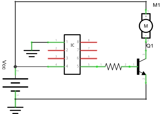
This configuration, called common emitter, is getting better, but there’s still something needed to be done. The motor is a typical inductive load, and when the transistor tries to open the circuit, the motor will try to keep going, forcing a current in the transistor (which is bad and will likely damage it) and/or in the Arduino (which will cause random resets and damage the pins). Another improvement is to add a flyback diode, so that the current has somewhere to go when the circuit is open.

There. It probably isn’t finished here, but it’s getting on the safe side. Then you might want to drive the motor in reverse, vary its speed, but this will probably be discussed in another post.
(Credits: graphics in this page were drawn with Fritzing.)
Lithium-ion batteries are everywhere and they are awesome also for hobbyist projects. I’ve been tempted more than once to use old smartphone batteries in my projects, but recharging them might be a problem.
Well, this time I tried my hand at recharging small coin-cells like the LiR2032. I’ve been looking around for commercial chargers, but they seem to be kind of unpopular. Turns out you can do one yourself with less than 2€.
The TP4056 (datasheet here) is a little IC which serves the purpose perfectly and currently it can be found on dx.com along with an additional protection circuit for 1.57€. However, this version comes pre-packaged to work with bigger batteries (>1000 mAh) and shouldn’t be used with coin-cells. Lets see why.
The difference lies basically in the charger’s maximum charging current. The previously linked TP4056 uses 1A maximum current, but LiR2032 datasheet recommends a maximum of 35mA. This current is regulated by a resistor placed between pin2 and ground on the charger (which on this board is called R1 and has a value of 1.2kohms). So, looking at the datasheet and doing the maths it turns out a resistance of about 35kohm is needed.
Okay. let’s go. I used
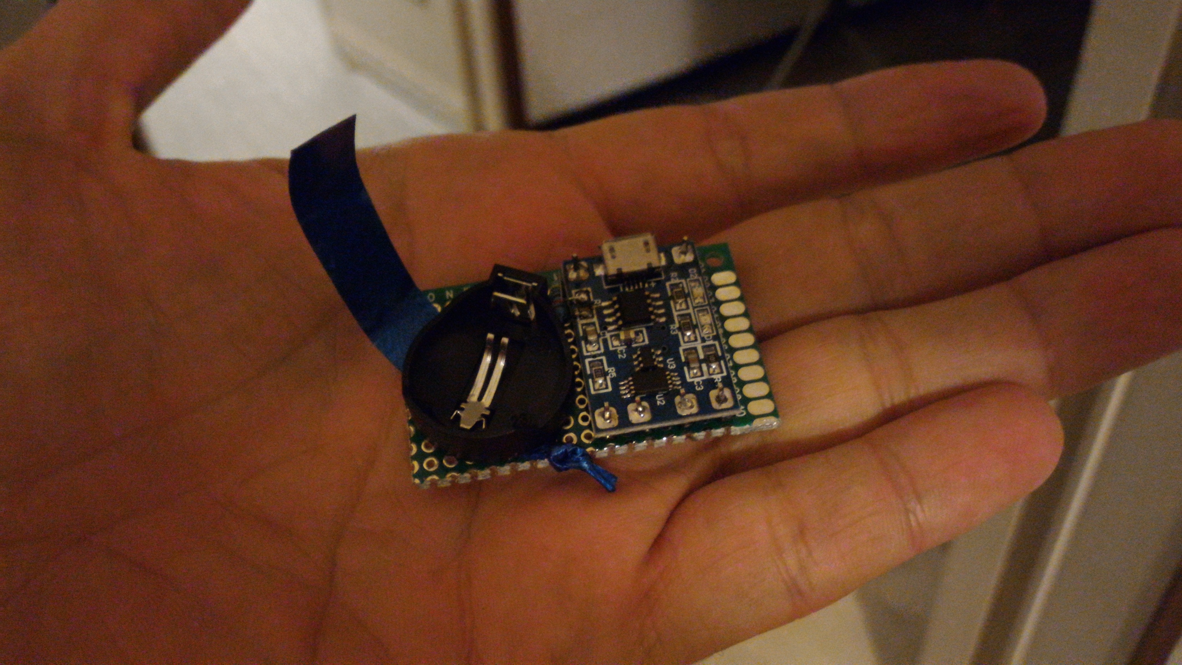
The assembling is quite straightforward, I just cut the PCB to size, mounted the TP4056 board on male pin headers, and mounted the coin cell holder over the ribbon, which I added for easier removal of the battery.
I didn’t have a 35Kohm SMD resistor available, so I replaced the old one with a “regular” 47Kohm resistor. Charging will be slower, but basically the slower the better. Soldering was doable although not trivial, a good set of pliers and tweezers definitely did help.

I soldered the wiring on the back… double check for correct polarity.

And voila. Charging an almost completely drained out battery took about 3 hours, during which all the assembly stayed at room temperature (based on a very accurate measurement with my fingers). Green light means charging done.

I still have to figure out exactly how to use this thing with bigger batteries, the main issue being find a way to keep the battery still. This is probably not going to be trivial since Li-ion batteries tend to come in every shape and size. Maybe I could use cable ties or rubber bands… I’m taking suggestions!

You must be logged in to post a comment.