I just launched Fonts Moods, a crowdsourced attempt at matching fonts with sentiment. You are welcome to collaborate or peek through the results!
Welcome to spaghettiwires.com!
I just renamed my blog from simonebaracchi.eu to spaghettiwires.com. Hope you like the new name!
How to not drive a motor with an Arduino
If you are like me, when you were an absolute beginner, you tried to wire a motor up to some batteries, saw the motor was spinning, and thought out loud: “It’s working! How hard could it be to turn it on and off with an Arduino?”
Actually a little more than it seemed at first. There are several problems I encountered and slowly fixed, and I’ll try to sum up in this post the kind of iterative reasoning that led to a decent circuit design.

So, first thing you try is to attach the battery poles to the motor, keeping the wires in place with your fingers. Everything seems to work fine! So what’s next? What’s the most obvious attempt to control it?

The second step would be to add a switch. Pushing the switch makes it run, release the switch and it stops. Perfect: now you just have to use an Arduino to open and close that switch.

This might be the most obvious change for a beginner, but also a very very bad idea. All the current is passing through the Arduino which is, in best cases, limited at 40mA, while even a very small motor will probably need way more than that. This might work for very very small motors but overall you risk damaging the pins.

So a “better” (but still bad) idea is to use a transistor instead! The configuration above is called emitter-follower. After all, transistor are like switches, and you have a lot of 2n2222 lying around, and they are a buck a kilogram, so why not make use of them? And maybe this circuit is kind of working, but it has at least two issues you should be considering now:
- What is the current required by the motor? Check the datasheet, and remember it probably needs a way higher amount when it is starting from a still position. The 2n2222 has a maximum rating of 500mA which might not be enough even if your motor is rated to consume only, say, 100mA. A cheap option would be to use a Darlington pair (basically, more transistors), but a better choice would be to use a different transistor which can bear a bigger current, like a MOSFET (e.g. a IRF510, still cheap and easily available) or possibly a relay. (As you probably know there are several models of BJTs, MOSFETs and relays and I’m pretty sure someone skilled enough could write a book about proper choice of this part).
- the other issue is that a part of the current is still sourced through the Arduino, so before burning something for good, a nice idea would be to add a resistor for protection, so that the maximum current flowing out of the Arduino is limited. (This is probably not an issue if using a MOSFET).

This will add some protection to the Arduino, but really, why risk? We can change the circuit so that none of the current flowing from the Arduino actually goes to the motor.
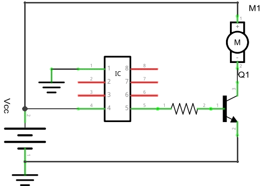
This configuration, called common emitter, is getting better, but there’s still something needed to be done. The motor is a typical inductive load, and when the transistor tries to open the circuit, the motor will try to keep going, forcing a current in the transistor (which is bad and will likely damage it) and/or in the Arduino (which will cause random resets and damage the pins). Another improvement is to add a flyback diode, so that the current has somewhere to go when the circuit is open.

There. It probably isn’t finished here, but it’s getting on the safe side. Then you might want to drive the motor in reverse, vary its speed, but this will probably be discussed in another post.
(Credits: graphics in this page were drawn with Fritzing.)
My experience with Soylent alternatives in Europe so far
Unfortunately in Europe there are no Soylent resellers. There are, however, quite a bunch of less famous alternatives. I’ve been asked about them a couple of times so I felt it was worth a blog entry.
I’ve been trying Soylent alternatives since November 2015, replacing about 30-40% of my meals. I had the chance to try Jimmi Joy (formerly Joylent), Huel, Mana, Nano, Jake and Futricio (formerly SoylentLife) and here are some of the differences between them.
Jimmi Joy: it is the one I’ve been recommending to everyone wanting to try out Soylent alternatives. Jimmi Joy is probably the one with the less barriers to entry. It is one of the cheapest, it comes with a handy bottle, it leaves a good fullness sensation and has a good variety of the best flavors. Cons: it tastes really better if you either blend it or leave it to rest for 8 hours or more, and variety is limited to its 5/6 flavors as there is no “unflavoured” option. Jimmi Joy also offers a “sports” version, and their bars are legit.
Mana: I’m more cautious in recommending it to beginners, since I feel it needs a little more experience to appreciate. Pros: very good ingredients (almost completely natural, and all of them are laboratory tested), has a good fullness sensation, and is almost unflavored, meaning you can add whatever flavor you want; this gives Mana the best flavor variety, in a way. Cons: it’s one of the most expensive, their bottle is not up to par with the others, and preparing it needs some more dedication.
Huel: I find this an excellent product, and the mix of different flours (oats, pea, and flaxseed) is very interesting. Pros: free shirt, good bottle, 30-30-40 macros ratio, cheap, comes in unflavoured variety, best “fullness” sensation yet, can be used for baking (not tried). Cons: does not dissolve easily (a spoon helps a lot), it is REALLY flavourless, needs a lot of flavours added (which they luckily sell along it). It is a great product if you want to stick to the unflavoured variety (and add some flavors yourself, but again, it’s dedication for such a product), otherwise the vanilla variety gets old after a while.
Jake: I have been trying their Sports variety because of the added protein contents, but after all it didn’t make me feel like I really needed them. Pros: good bottle included, single portion bags are very easy to prepare, and good vanilla flavor. Cons: only vanilla is available, and it didn’t make me feel really “full”. After a while I was craving for something different. Overall I think I could recommend it for casual use, but not for every day.
Nano: it is very similar to Jake (they share vanilla, pea flour, and crushed flaxseed as ingredients). Pros: less flavoured than Jake, you can actually add other flavours for variety, better “full” sensation than Jake, single portion bags. Cons: the included bottle is hard to clean, and it never makes me feel really “full”, just like Jake.
Nano Veggie: it is a unique product as it’s meant to be consumed hot. It has a quite interesting spicy tomato soup consistency. Pros: unique taste, single portion bags. Cons: only one flavour, and the same downsides as regular Nano.
Futricio: I was not satisfied with this. Pros: bottle included, single portion bags, 5 flavors available. Cons: flavors are not as good as Joylent ones, and it didn’t really make me feel “full”.
There are a couple of others I did not try out: Queal, Bertrand, and so on. Other reviews have not encouraged me to do so, but if somebody wants to trade bags, I’m open.
I also compiled a list of ingredients easily found in Italy, and attempted to make a recipe out of those (with an simple optimization tool I wrote), but still haven’t had a chance to try it out.
Anagrhash, a anagram generator & reverse hash searching tool
Anagrhash is a tool which can generate anagrams, and test them against a hash.
It is a tool I wrote many years ago for educative purposes, to try out some different concurrency models and inter-thread communication methods in C, and get some basics of programming in the GNU/Linux environment.
It serves as an anagram generator, and can shuffle letters, but can also be set to shuffle whole words in a sentence, use tokens from a list (words which you don’t want to appear simultaneously), and specify separators between tokens (like spaces or commas).
It can also test anagrams which satisfies an exact target hash, or a hash specified with a regular expression.
You can get it on my GitHub page.
xboxdrv 0.8.8 for the Raspberry Pi Zero
If you, like me, have just found out that GameStop xbox360 controllers, even when they have the same BB070-B-EU model, from the same shop, same look, same everything, … but they happen to have different chipsets, and not all of them work properly with xboxdrv 0.8.5; you might appreciate an update from the version which is offered in the Raspbian repositories.
In my case, the incompatible model was showing up with magic numbers 0e6f:0401 in `lsusb`. The GameStop xbox360 controllers which works with xboxdrv 0.8.5 shows up as 0e6f:0301.
Compiling it took quite a long time (about two hours), so here’s a precompiled package. You can get xboxdrv 0.8.8 in a .deb package for ARM here.
2€ charger for any kind of lithium-ion battery
Lithium-ion batteries are everywhere and they are awesome also for hobbyist projects. I’ve been tempted more than once to use old smartphone batteries in my projects, but recharging them might be a problem.
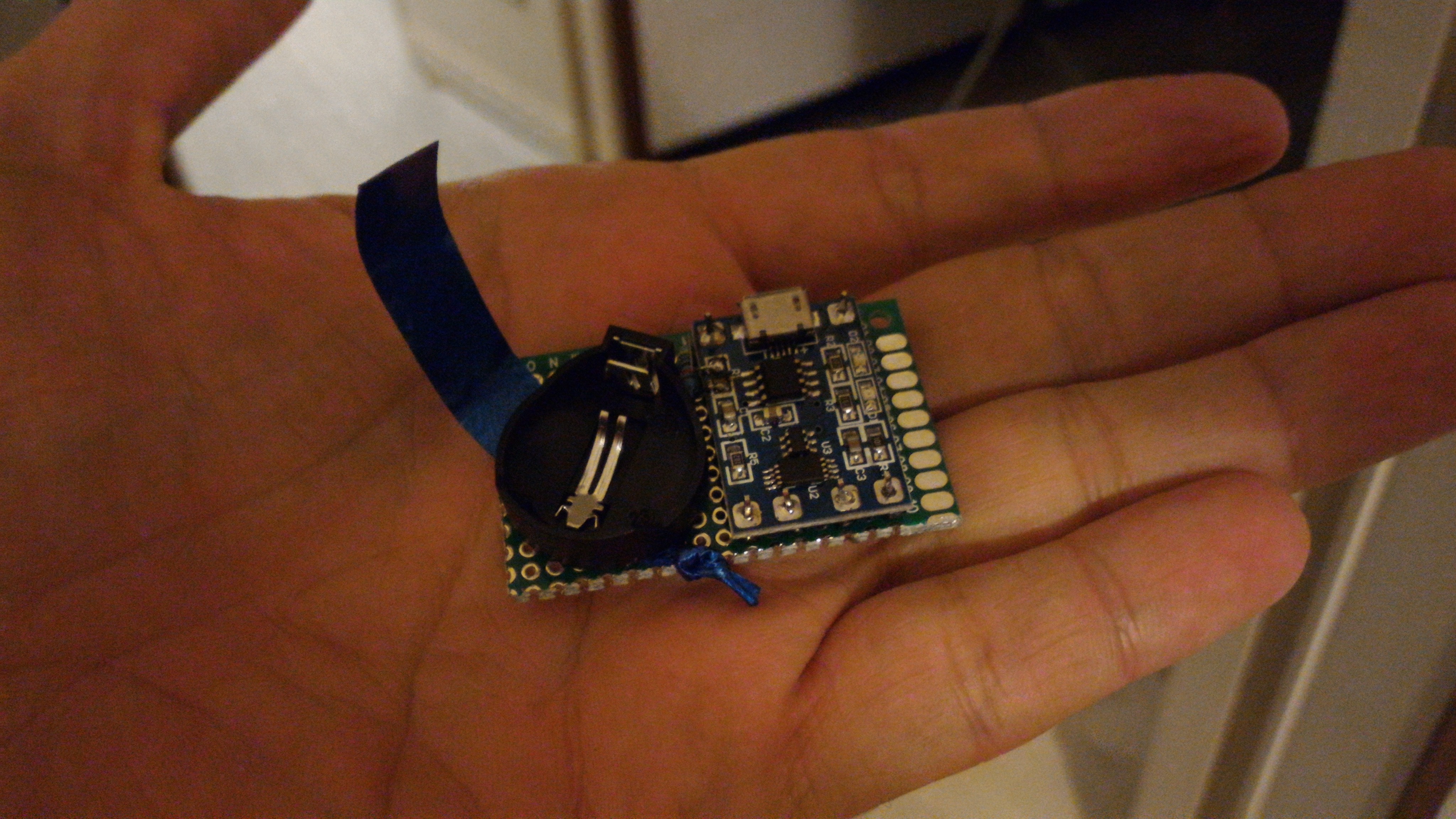
Well, this time I tried my hand at recharging small coin-cells like the LiR2032. I’ve been looking around for commercial chargers, but they seem to be kind of unpopular. Turns out you can do one yourself with less than 2€.
The TP4056 (datasheet here) is a little IC which serves the purpose perfectly and currently it can be found on dx.com along with an additional protection circuit for 1.57€. However, this version comes pre-packaged to work with bigger batteries (>1000 mAh) and shouldn’t be used with coin-cells. Lets see why.
The difference lies basically in the charger’s maximum charging current. The previously linked TP4056 uses 1A maximum current, but LiR2032 datasheet recommends a maximum of 35mA. This current is regulated by a resistor placed between pin2 and ground on the charger (which on this board is called R1 and has a value of 1.2kohms). So, looking at the datasheet and doing the maths it turns out a resistance of about 35kohm is needed.

Okay. let’s go. I used
- the TP4056 board,
- a coin cell battery holder,
- a 47Kohm resistor
- a 10cm ribbon
- some pin headers, wire, PCB and soldering
The assembling is quite straightforward, I just cut the PCB to size, mounted the TP4056 board on male pin headers, and mounted the coin cell holder over the ribbon, which I added for easier removal of the battery.
I didn’t have a 35Kohm SMD resistor available, so I replaced the old one with a “regular” 47Kohm resistor. Charging will be slower, but basically the slower the better. Soldering was doable although not trivial, a good set of pliers and tweezers definitely did help.

I soldered the wiring on the back… double check for correct polarity.

And voila. Charging an almost completely drained out battery took about 3 hours, during which all the assembly stayed at room temperature (based on a very accurate measurement with my fingers). Green light means charging done.

I still have to figure out exactly how to use this thing with bigger batteries, the main issue being find a way to keep the battery still. This is probably not going to be trivial since Li-ion batteries tend to come in every shape and size. Maybe I could use cable ties or rubber bands… I’m taking suggestions!
The online replacement vs repair decision helper
I wrote this tool to help decision-making when you have have to repair or replace something.
It uses a pair of jeans as an example, but it’s meant to be generic. Just replace its parameters and let it calculate.
(I’m assuming as a currency and one as a time unit.
I also assume a %/year growth rate of your assets.)
| You are thinking about replacing a: | |
| You have owned pair of jeans for: | year(s) |
| Replacing the pair of jeans would cost you: | $ |
| Your pair of jeans is costing you in repairs: | $ / year |
| While the pair of jeans is undergoing repairs, you have a backup plan which costs you: | $ / year |
| Do you feel the pair of jeans at risk of a major, catastrophic, sudden failure? | |
| Not really. | |
| Possibly… but maybe an ice cream would cheer me up again. (+5 $ / year) | |
| I think I’ll have to pay a couple of fine dinners if that happens. (+50 $ / year) | |
| Well, that would cost me about $. | |
| Would a new pair of jeans have significant advantages, or technological advancements, over the old one? | |
| Not really. I’m kind of emotionally bonded to the old one. | |
| For starters, it wouldn’t look old. (+15% value over the old one.) | |
| It has an improvement or two. (+30% value over the old one.) | |
| The new one is way better! (+% value over the old one.) | |
Bluetooth low-energy temperature beacon using the nRF24L01: cheap and compatible with existing smartphone apps!
The reason I did this project is because I have a slight overheating issue in a server room; I was wondering if there would be some way to check another room’s temperature from my desk. That’s how I came up with a “wireless thermometer” that can send readings to my Android phone, and my colleagues can use it too!
You might have heard about the nRF24L01: it is a cheap (0.80€) radio frequency module that, back in 2013, Dmitry Grinberg was able to use to “fake” a BTLE beacon. Real Bluetooth 4.0 modules are, nowadays, about 5€ each.
I wondered if I could use it to make a BTLE compatible temperature beacon. Turns out there are 3 major BTLE beacon protocols: iBeacon (by Apple), Eddystone (by Google), and AltBeacon (by Radius Networks). And well, none of them can be emulated with the nRF24L01, since it is only able to send a 16-byte payload (among other limitations), and all three of those protocols require bigger PDUs.
BUT!!! Although I didn’t find a name for it, Nordic Semiconductors Bluetooth ICs (namely the nRF8001 and nRF51822) have their own protocol they use to send telemetry data (which means: temperature, battery level and device ID); turns out this protocol is simple enough to be emulated by the nRF24L01 as well, although with some limitations. They also are so nice to distribute a suite of Android and iOS apps to work with them; the most relevant apps are nRF Master Control Panel (useful for debugging BTLE devices) and nRF Temp 2.0 (a temperature logger; I think it was meant to track device overheating, but hey). You can also download the source code from the app page!


However, the temperature in my room is quite boring, as shown from those screenshots of Nordic Semiconductors apps. (nRF Master Control Panel on the left, nRF Temp 2.0 on the right).
The temperature beacon hardware is very simple. Just wire up your microcontroller to a nRF24L01 and a temperature sensor of your choice (I used a DHT11 I had lying around).
 It’s more about how you wire them up, I guess.

(fabacademy.org)
- GND -> GND on the Arduino
- VCC -> 3.3v on the Arduino
- CE -> PIN 9 (see below)
- CSN -> PIN 10 (see below)
- SCK -> PIN 13 on the Arduino Uno
- MOSI -> PIN 11 on the Arduino Uno
- MISO -> PIN 12 on the Arduino Uno
- IRQ -> not used
Be especially careful about the power pin: altough the nRF24L01 can work with your 5v Arduino, you must power it at 3.3v!
While SCK/MOSI/MISO are pretty much wired to 13-11-12 pins in order to use SPI, CE and CSN can be moved to a pin of your choice.
About the DHT11, just wire its output pin to A0, and the other two to ground/+5v.
On the software side, I did a couple modifications on floe’s BTLE library to allow mimicking of the nRF8001 and nRF51822; you can find the BTLE library here. With this library, you can now create your temperature beacon. (Notice I used pins 9 and 10 as CE and CSN, as mentioned previously).
Did you know? Most Arduinos have an onboard temperature sensor! The reasoning behind this probably is that a device malfunction would overheat it. Unfortunately this can’t be easily used as an ambient temperature sensor, because the chip temperature is widely influenced by its heat dissipation. That’s why I used a DHT11. (You can read more about this on Arduino Playground here).
Among other limitations, this setup is not able to use more than 3 of the 40 BT 4.0 channels, and broadcast a name longer than 8 characters (remember that 16 byte limit?). I’m pretty sure it could be used to broadcast the battery level as well.
Sadly, it does not seem somebody has thought of writing a standard protocol for broadcasting some other non-temperature parameter (atmosphere pressure, light, noise level, etc). To a certain extent, nRF Master Control Panel can be used to receive arbitrary data from the Arduino (as float or as integer value), but it’s not suitable for logging and combined with the 16 byte limit it’s quite limited (BT also has a 2 bytes overhead for every field you want to send, hence: 8 bytes device name + 4 bytes temperature + 2*2 bytes of overhead = 16 bytes). If I’m wrong, let me know!
I hope you enjoyed this article!
The knock-activated noisy box
This project was intended as a prank; when I was thinking about the uses of a knock sensor I thought it would be funny to use it to make a doorbell. The thing you see is a small box that produces a funny chirping noise when you knock or shake it. It is intended to be attached to a door, or some other moving object. Not really an Arduino project since it uses only basic electronic components, but still it was quite entertaining to make and it’s a chance to have fun with analog electronics!
I used:
- a 6x4cm PCB (2.36″ x 1.578″) (obtained by cutting a bigger PCB)
- one CR2032 coin cell battery
- a ghetto coin cell battery holder… made out of a binder clip and some insulating tape
- a KY031 knock sensor
- a 470uF capacitor (the bigger the better, basically)
- an active 5V buzzer
- a very small project box I couldn’t find another use for (8x5x2cm, or 3.1x2x0.8″)
- wire and soldering iron
The circuit itself is very simple. When you bump the knock sensor, the circuit closes; the capacitor is charged (very quickly) and then slowly discharges thru the buzzer. Note that the knock sensor usually has a digital output/pull-up pin which I’m not using: the 10k resistor it has attached would make the capacitor charge too slowly.

The assembly is quite straightforward or in other words I forgot to take pictures of the process.

This is the final circuit. As you can see I used a binder clip for lack of a better coin cell holder… I stole the idea from here. Then I soldered the clip to the PCB. I tried to leave some room in front of the battery to make replacement easier. The cables go from the battery to the back.

The wires on the back make the soldering quite easy. Just solder the knock sensor in series to everything else (green wire – going to ground on the other side), and the capacitor and buzzer (bottom left) together in parallel. Double check the capacitor polarity (red wire goes to Vcc on the other side). I used velcro to attach the PCB to the box; very handy if you, like me, never have available screws of the right size.

The box is just of the right size for the half PCB.

They couldn’t fit any better.

As I mentioned, the box is very small, almost matchbox-sized. The idea is to glue it (maybe with velcro, I like that stuff) to a door or another moving object you want to produce a “pew” sound when you knock or move it.
Some things I learned today:
- Maybe I should buy a proper coin cell holder.
- If nothing else, I should have mounted the ghetto holder the other way around.
- Wires are best cut at the exact length you need them.
- The KY031 is REALLY poorly sensitive, you have to shake it really hard. They should call it the car crash sensor or the ground-reached-after-freefall sensor or the shake-as-hard-as-you-can sensor or something. It has a very very precise impact angle at which it is somewhat sensitive. I should get a more sensitive vibration sensor, I’ve been looking around and afaik you have these alternatives:
- a SW-18010; yes I should point to the datasheet but according to this YouTube video it doesn’t look significantly more sensitive than the KY031. (the SW-18030 should be even less sensitive, and I couldn’t find much about the SW-58010).
- a KY002, but it looks to be a PCB with a sw-18015 mounted on it.
- a 801S, but it looks somewhat more costly and not usable as a switch.
- a HDX2 (also called SW-420 or HDX1 (??)), it looks very sensible according to YouTube but it’s “normally closed”; this would require some signal conditioning and more power consumption.
Anyway, the final result for this article is this weird bleeping thing! I hope you enjoyed it!
You must be logged in to post a comment.