If you are like me, when you were an absolute beginner, you tried to wire a motor up to some batteries, saw the motor was spinning, and thought out loud: “It’s working! How hard could it be to turn it on and off with an Arduino?”
Actually a little more than it seemed at first. There are several problems I encountered and slowly fixed, and I’ll try to sum up in this post the kind of iterative reasoning that led to a decent circuit design.

So, first thing you try is to attach the battery poles to the motor, keeping the wires in place with your fingers. Everything seems to work fine! So what’s next? What’s the most obvious attempt to control it?

The second step would be to add a switch. Pushing the switch makes it run, release the switch and it stops. Perfect: now you just have to use an Arduino to open and close that switch.

This might be the most obvious change for a beginner, but also a very very bad idea. All the current is passing through the Arduino which is, in best cases, limited at 40mA, while even a very small motor will probably need way more than that. This might work for very very small motors but overall you risk damaging the pins.

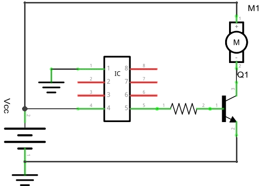
So a “better” (but still bad) idea is to use a transistor instead! The configuration above is called emitter-follower. After all, transistor are like switches, and you have a lot of 2n2222 lying around, and they are a buck a kilogram, so why not make use of them? And maybe this circuit is kind of working, but it has at least two issues you should be considering now:
- What is the current required by the motor? Check the datasheet, and remember it probably needs a way higher amount when it is starting from a still position. The 2n2222 has a maximum rating of 500mA which might not be enough even if your motor is rated to consume only, say, 100mA. A cheap option would be to use a Darlington pair (basically, more transistors), but a better choice would be to use a different transistor which can bear a bigger current, like a MOSFET (e.g. a IRF510, still cheap and easily available) or possibly a relay. (As you probably know there are several models of BJTs, MOSFETs and relays and I’m pretty sure someone skilled enough could write a book about proper choice of this part).
- the other issue is that a part of the current is still sourced through the Arduino, so before burning something for good, a nice idea would be to add a resistor for protection, so that the maximum current flowing out of the Arduino is limited. (This is probably not an issue if using a MOSFET).

This will add some protection to the Arduino, but really, why risk? We can change the circuit so that none of the current flowing from the Arduino actually goes to the motor.
This configuration, called common emitter, is getting better, but there’s still something needed to be done. The motor is a typical inductive load, and when the transistor tries to open the circuit, the motor will try to keep going, forcing a current in the transistor (which is bad and will likely damage it) and/or in the Arduino (which will cause random resets and damage the pins). Another improvement is to add a flyback diode, so that the current has somewhere to go when the circuit is open.

There. It probably isn’t finished here, but it’s getting on the safe side. Then you might want to drive the motor in reverse, vary its speed, but this will probably be discussed in another post.
(Credits: graphics in this page were drawn with Fritzing.)
You must be logged in to post a comment.